Atmega328 with RTC and Sleep mode
Introduction
In this post I will explain how to use the RTC MCP7940 in an Atmega328 Breadboard with the sleep mode, waking up with a button as interrupt.
As I see in my homemade watch, two of the biggest problems were; the time measured, which was not enough precise to be a watch (I lost 10 minutes per day!) and the battery consumption, which spend a CR2032 battery with 240 mAh in only 3 days.
Bill-Of-Materials
RTC
- RTC MCP7940M
- Crystal 32.768kHz
- 2 x 6.8pF capacitor
- 2 x 4.7k resistor Atmega
- Atmega328
- 1 x 10k resistor (pullup resistor for reset pin)
- 1 x 200-300 resistor (for the led)
- 1 x Led
- 1 x FTDI Serial communications Button interrupt
- 1 x 10k resistor (pull down resistor)
- 1 x Button
Instructions
Atmega328
Get the Atmega328 and put it in a Breadboard. Place the pull up 10k resistor for the reset pin, and the resistor and led to the Arduino pin 13 (atmega pin19).
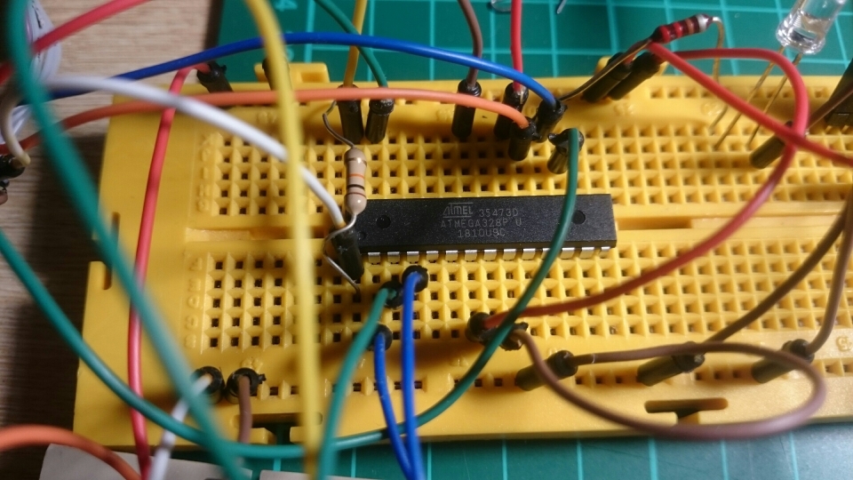
Burn the bootloader with the internal clock 8Mhz and program the blink example. You have everything explain in these previous entries, ArduinoToBreadboard-v2.html and ArduinoToBreadboard.html
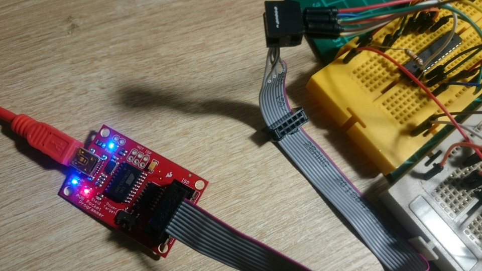
For burning the bootloader and programming, I’ve used this time a programmer instead of an Arduino as ISP: The pocket AVR programmer from sparkfun.
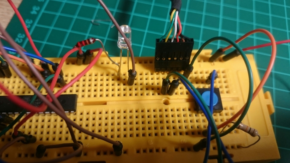
Button
Connect the button with one pin to VCC, and the other to the 10k pulldown resistor to GND and to the Arduino pin2 (interruption pin). In the atmega328, pin 4. You have small tutorial and example code in arduino webpage
RTC MCP7940M and Crystal 32.768kHz
Once the basic setup is installed, it’s time to test the RTC.
And if you are wondering: Why this frequency exactly? Well, sparkfun has a definition in the web
Crystal 32.768kHz: Standard ‘Watch’ or Real-Time-Clock crystal. 32.768kHz means it is precisely half of a 16-bit counter. Start counting at 0x8000 (or 32768). When the counter rolls over from 65535 to 0, then you know that exactly one second has passed. Reset the interrupt, reset the counter, and start counting again!
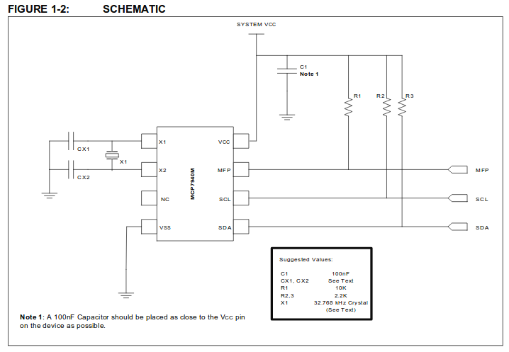
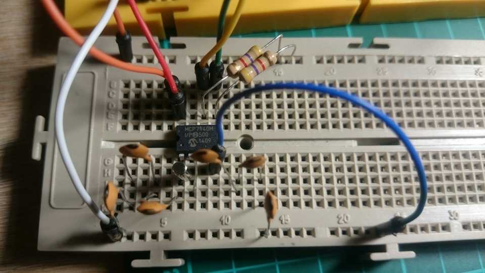
For the setup, I’ve followed the schematic from the MCP7940M datasheet,
But not exactly the same, because I also have another schematic from a library to use this RTC,
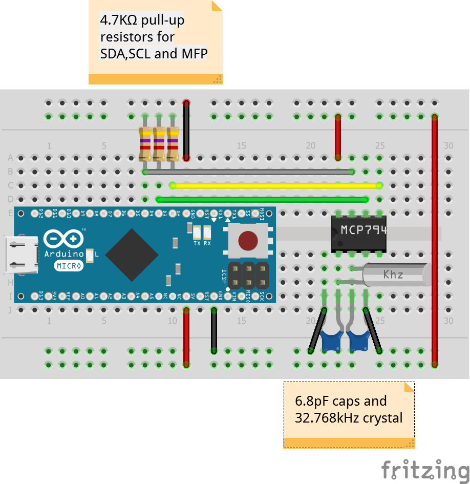
My schematic is not exactly elegant, because I’ve used 3 capacitor 22pF in series for achieving the ~6.8pF ( 1/(1/22+1/22+1/22) = 7.33 pF ) and for me it wasn’t necessary the MFP pin (Used for alarms)
The SCL and SDA pins in the Arduino are the A5 and A4, or in the atmega328 the latest pin (28, 27)
MCP7940M Software Testing
I’ve use a great library for using this RTC. There are some examples but basically, it just necessary if we use:
#include <MCP7940.h>
MCP7940_Class MCP7940;

void setup()
{
    ...
    MCP7940.begin();
    MCP7940.deviceStart();
    MCP7940.adjust(DateTime(2018,11,7,21,39,10));
    ...
}

void loop()
{
    ...
    DateTime now = MCP7940.now();
    ...
}
FTDI Serial communications
If you want to see what is happening when you do a “println” in the atmega328, you should have some serial communication.
For the FTDI, following the schema,
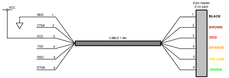
You have to connect only three cables:
- RX FTDI to TX atmega328 (Pin 3)
- TX FTDI to RX atmega328 (Pin 2)
- Common GND
Software
Once everything is tested, the only thing missing is the sleep mode of the atmega328. For that, I’ve used the Arduino Low Power library
The complete software for this test (Also available in my github)
#include <Arduino.h>

#include "MCP7940.h"
#include "LowPower.h"

// Constant
const int BUTTON_PIN = 2;    // Button For interruption
const uint8_t  SPRINTF_BUFFER_SIZE = 32;
const int SERIAL_ACTIVE = 1;

// Variables
MCP7940_Class MCP7940;
char inputBuffer[SPRINTF_BUFFER_SIZE];

static uint8_t secs;

// Function wakeup
void wakeUp()
{
    // Just a handler for the pin interrupt.
}

void setup()
{
    // Led output
    pinMode(LED_BUILTIN, OUTPUT);

    // Serial output
    if(SERIAL_ACTIVE == 1)
        Serial.begin(9600);

    // RTC
    while (!MCP7940.begin())
    {
        if(SERIAL_ACTIVE == 1)
            Serial.println(F("Unable to find MCP7940M. Checking again in 3s."));
        delay(3000);
    }

    if(SERIAL_ACTIVE == 1)
        Serial.println(F("MCP7940 initialized."));

    while (!MCP7940.deviceStatus())
    {
        if(SERIAL_ACTIVE == 1)
            Serial.println(F("Oscillator is off, turning it on."));

        bool deviceStatus = MCP7940.deviceStart();
        if (!deviceStatus)
        {
            if(SERIAL_ACTIVE == 1)
                Serial.println(F("Oscillator did not start, trying again."));
            delay(1000);
        }
    }

    //MCP7940.adjust();   // Adjust time with the compilation time
    MCP7940.adjust(DateTime(2018,11,7,21,39,10));   //Set a specific time

    delay(2000);
}

void loop()
{

    // Allow wake up pin to trigger interrupt on low.
    attachInterrupt(0, wakeUp, HIGH);

    // Enter power down state with ADC and BOD module disabled.
    // Wake up when wake up pin is low.
    LowPower.powerDown(SLEEP_FOREVER, ADC_OFF, BOD_OFF);

    // Disable external pin interrupt on wake up pin.
    detachInterrupt(0);

    // Do something here after wake up until next loop to sleep

    DateTime now = MCP7940.now();

    if (secs != now.second())
    {
        sprintf(inputBuffer,"%04d-%02d-%02d %02d:%02d:%02d", now.year(),
            now.month(), now.day(), now.hour(), now.minute(), now.second());

        if(SERIAL_ACTIVE == 1)
            Serial.println(inputBuffer);

        secs = now.second();

        // Toogle the led when reading time
        digitalWrite(LED_BUILTIN, HIGH);
        //digitalWrite(LED_BUILTIN,!digitalRead(LED_BUILTIN));
        delay(4000);
        digitalWrite(LED_BUILTIN, LOW);
    }

    delay(2000);
}
Comments
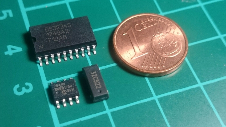
Others RTC I’ve been considering were:
- DS3234
- MCP79410, which I guess from the same family as the MCP7940 I use.
- DS1307
- Or we could use even the 32.768 Crystal directly, as the sparkfun did with this watch.
If I’ve decided of using an IC for the RTC instead of using the crystal directly is because I will prefer just consult the time instead of calculate the time based on the frequency and so on.
And the biggest difference between the DS1307 and MCP7940 with the DS3234 is, this last one, includes the crystal and it is more accurate and less sensible to the external temperature. But it also 10 times more expensive than the MCP7940.
You can see a good tutorial comparing both
And also, you could chose one or the other depending where you want to put it. The size of the DS3234 is quite big compare with the others.
Current consumption and final results
The Arduino sleep mode works very well, even if I don’t reach the same values of the specification:
According to the specification, Power Consumption at 1MHz, 1.8V, 25 degrees.
- Active Mode: 0.2mA
- Power-down Mode: 0.1μA
- Power-save Mode: 0.75μA (Including 32kHz RTC)
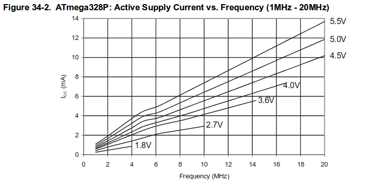
According to ATmega328P Typical Characteristics,
Active mode 3V at 1Mhz: ~0.5mA

Active mode 3V at 8Mhz: ~3mA
Actual consumption
3V @ 8MHz
- Active + 1 led: 4.6mA
- Active: 3.1mA
- Powerdown: 1.15 μA
3V @ 1MHz
- Active + 1 led: 2.46mA
- Active: 0.82mA
- Powerdown: 1.15 μA
In the following video, I use the 5V from the FTDI with atmega328 at 1Mhz. We can see the three modes, powerdown, active with led, and active. Also, when we open the serial port to see the timing, it consumes a little more (And the time was not set correctly!)