Arduino To Breadboard: Atmega328p
Introduction
In this post I’ll explain how to use the Atmega328p (aka as the core of the Arduino Uno) for using in a Breadboard and programming with the Arduino bootloader.
Motivation
I don’t hate Arduino. In fact, I like so much, and as lot of us, I’ve started the microcontrollers world from this microcontroller to the basic ones. While a real electronics should start from the basic digital microchips to another more complex, Arduino allows to skip some steps, and go forward or backward to the knowledge of electronics… =D
But, there are several reason you may decide use the microcontroller (Atmega) directly instead of the Arduino itself:
- Size: You may not need all the pins or all the elements that contains the Arduino, but it is more valuable the size where you want to use for your project. Basically, with the Atmega328p you will need an external clock, two capacitors.. and that’s it!
- Integration: It could be the reason more usual because, instead of develop an specific PCB to act as a shield of the Arduino, you want to solder the Atmega328p with the other components that you will use for your circuit.
- Power saving: This is an affirmation I am not sure is correct, because, normally you will save more power if you are not using the leds included in the Arduino (power Led, the Led 13..), you are not using the LD Power converter.. But you will need one, because the Atmega328p should be powered by 5V (except if you are using a standard power supply from a mobile phone, and you trust enough in that). So, I am not sure if it is worth it. If you want to see some tips to save power with an Arduino, you can see this blog
- Price: If your motivation is the economic cost of using an Atmega328p in comparison with the official Arduino Uno, you are right, you could save some money. But on the other hand, there are unofficial Arduinos that could be good enough for you, and all the elements that could cost the Arduino homemade could be the same as the unofficial Arduino.
Elements
- 1 x 16 MHz crystal or 8Mhz if it is your option.
- 1 x 10k resistor
- 2 x 18 to 22 pF (ceramic) capacitors
- 1 x 0.1uF capacitor
- 1 x Arduino to update the Bootloader.
- For programming: FTDI cable or the same Arduino extra, if it is the rev2 or less (You can use the UART from Arduino for progremming, but your Atmega328p has to be umounted. In the rev3, it is a SMD you can’t remove)
- 1 x Led to verify the blink program loaded.
It is not necessary all the element listed here. You may not need the external clock of 16Mhz (therefore, neither the 22pf capacitor) and use the internal clock. If you are using the extra Arduino for programming, you may not need the 0.1uF capacitor (Used for the RST in the FTDI connection)
Burnin the Bootloader using Arduino as ISP
You could follow the official tutorial from Arduino
Copy-paste the steps..
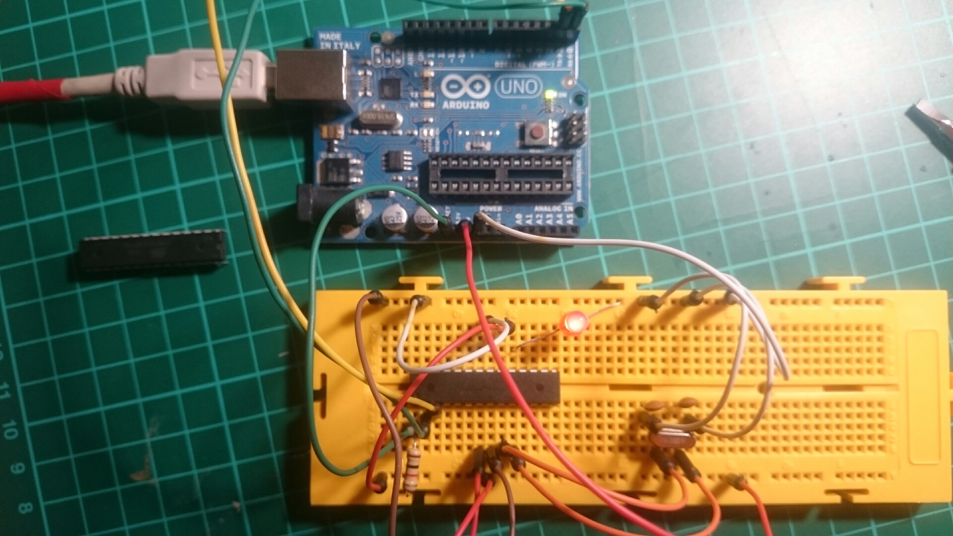
- Upload the ArduinoISP sketch onto your Arduino board. (You’ll need to select the board and serial port from the Tools menu that correspond to your board.)
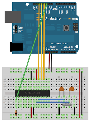
- Wire up the Arduino board and microcontroller as shown in the diagram to the right.
- Select “Arduino Duemilanove or Nano w/ ATmega328” from the Tools > Board menu. (Or “ATmega328 on a breadboard (8 MHz internal clock)” if using the minimal configuration described below.)
- Select “Arduino as ISP” from Tools > Programmer
- Run Tools > Burn Bootloader
- You should only need to burn the bootloader once. After you’ve done so, you can remove the jumper wires connected to pins 10, 11, 12, and 13 of the Arduino board.
You could find additional information about the Arduino ISP in this link
The sketch also supports three LEDs that give you a visual feedback about the programming process (Pins 7,8 and 9)
Programming the Arduino
Once you have the bootloader inside the Arduino, you can program from different ways:
Using an external Arduino
Again, in the official tutorial you can find the method.
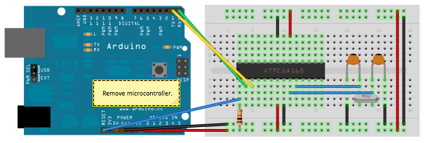
To program the microcontroller, select “Arduino Duemilanove or Nano w/ ATmega328” from the the Tools > Board menu (or “ATmega328 on a breadboard (8 MHz internal clock)” with minimal configuration). Then upload as usual.
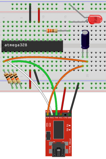
Using FTDI cable.
This could be useful if you don’t have an external Arduino, or you can not remove the Atmega328p from it. Also, if you want to have the pinout for programming easily accesible.
You can follow the steps in this blog
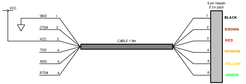
For some reason, the FTDI this tutorial uses has the RX/TX inverted in my FTDI cable. So, you should see the specification of your FTDI chip before of programming (If not, you could have the error of not communication)
In my case, the FTDI cable specification
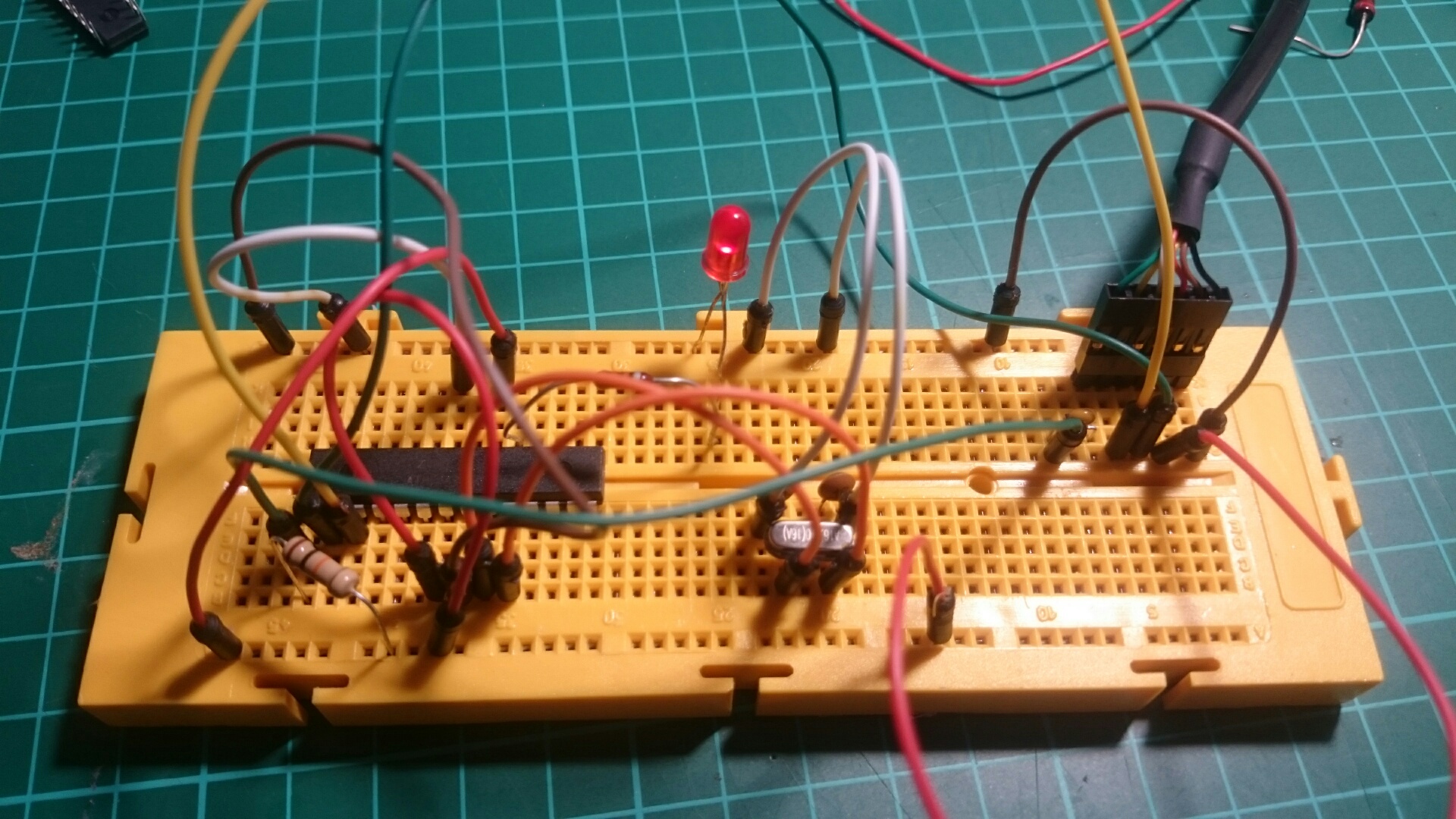
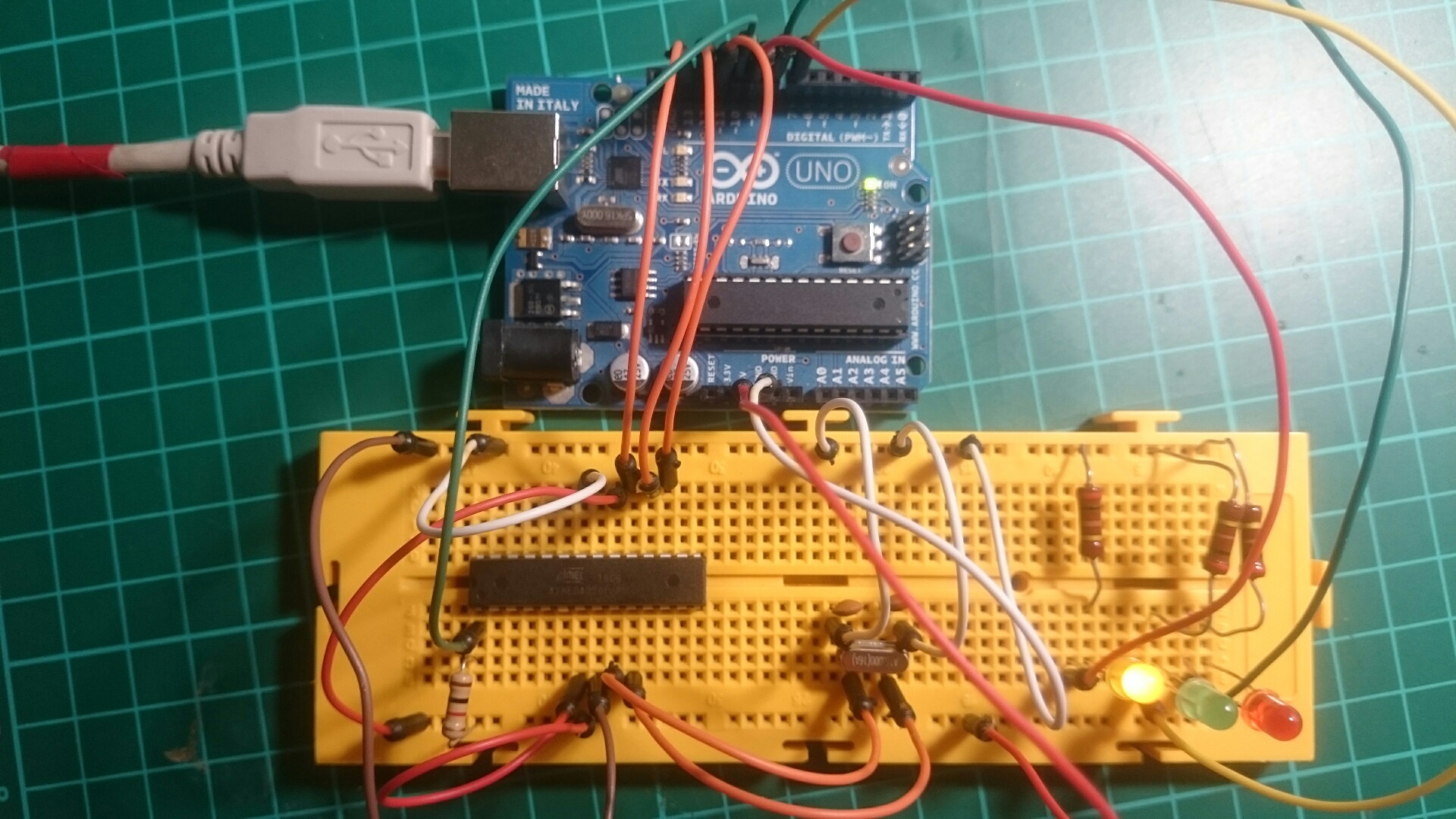
Blink!
Connect the LED to the famous 13th pin from the Arduino (Wait!! The pin in the Atmega328p which correspond to the PIN13 is the Pin 19) and load the Arduino helloworld blink program (don’t forget to change to the board Arduino Duemilanove w/ ATmega328).
The power could come from the FTDI / the other Arduino, which you used to program.
Powering
At this point, you have an Arduino with the bootloader, a helloworld program, but powered from FTDI or another Arduino. Let’s rid of that also.
We will need:
A good tutorial to how to use this voltage regulator is this one
A better one could be the datasheet of the component.
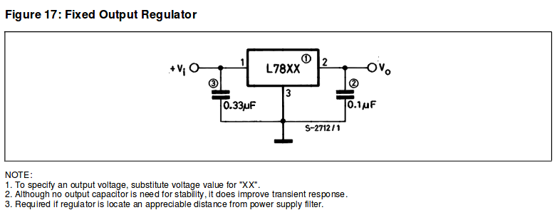
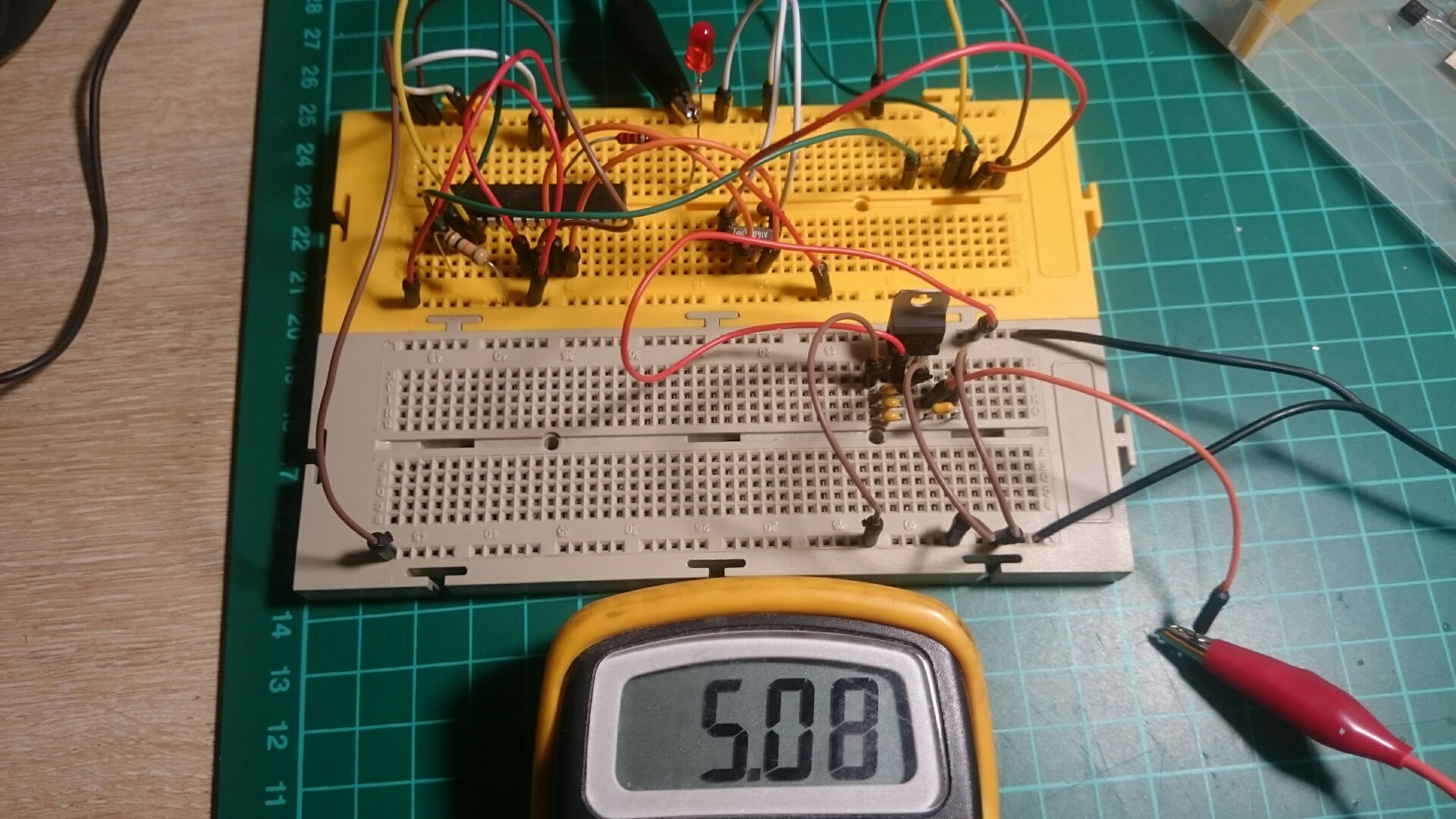
The input could be any voltage from 8V to 20V according the datasheet. That could be a 12V power supply or a 9V battery, for example. You should test the 5V voltage in the third pin before to connect to the circuit.
Another tutorial you could use since program the Arduino to powering is this instructable.
Explore
You have now everything you need to continue your project! Only take a look of the datasheet for the Atmega328p and you are ready!
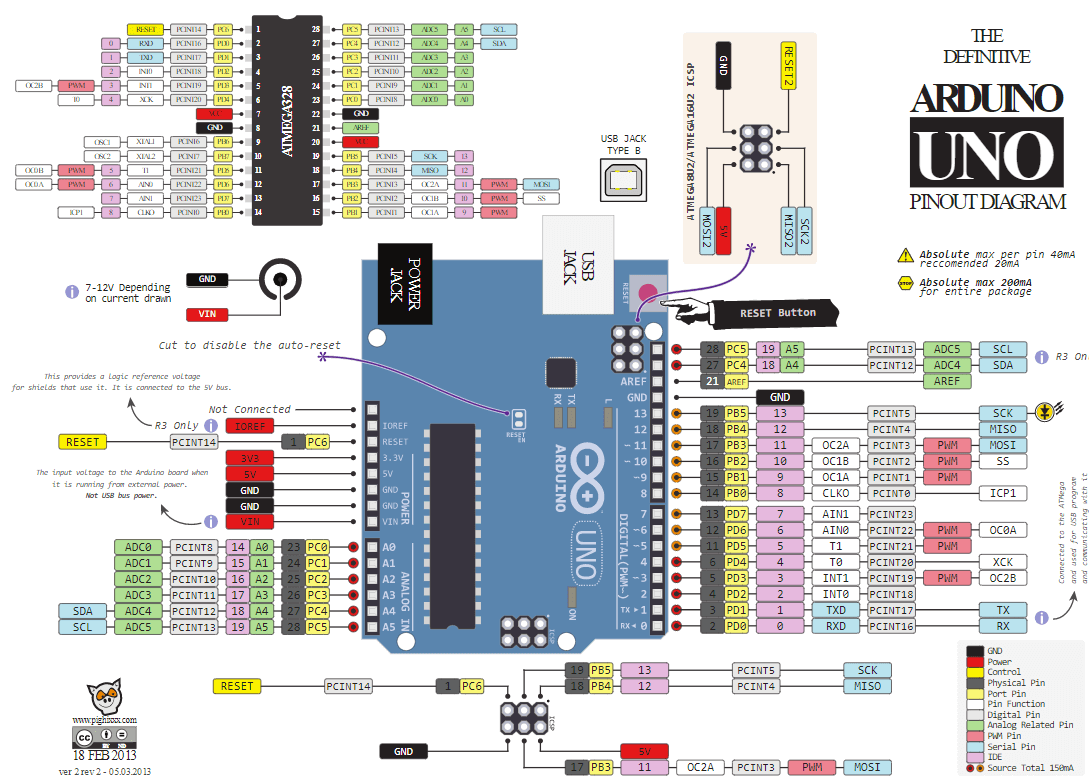
You can find a good pinout diagram from circuito.io blog