Bora Watch - A simple and geek homemade watch
Introduction
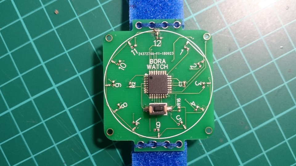
Hey, I’ve made my own watch!
One day, I was really impressed with the project I saw in hackaday. A project created by electronoobs with internal clock using the atmega328p, 12 leds and resistors, 3V battery and very few components more.
So, as it was well documented with all the list of materials, design files and so on, I decided to made it.
The challenges I had with the project were basically two;
- Using the atmega328p with the internal clock (Until now, I got rid of the Arduino components for using only the core, the atmega328 and a few components, but not using the internal clock)
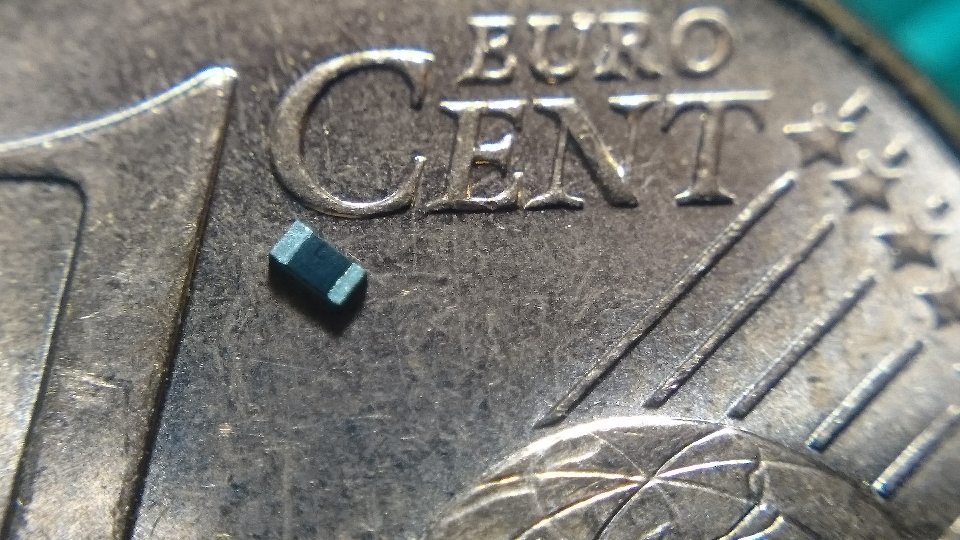
- And, the really challenge here, the SMD soldering
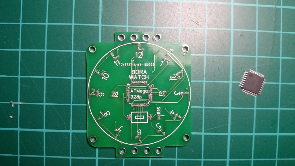
Example of components size,
Bill-Of-Materials
- 1 x PCB: GERBERS here, schematics and board. Designed here and manufactured here
- 1 x ATMega328p-AU: Amazon Atmega328p. Bought here because my usual provider didn’t have.
- 12 x 200R 0402 SMD resistors: Distrelec 200 0402
- 12 x 0402 SMD LED: Distrelec Led 0402
- 1 x SMD Tactile Switch: Distrelec Button
- 2 x 10K 0402 SMD resistors: Distrelec 10k 0402
- 1 x 100nF 0402 SMD capacitor: Distrelec 100nF 0402
- 1 x 10uF 0805 SMD capacitor: Distrelec 10uF 0805
- Battery Holder CR2032 Distrelec Battery Holder
Tools
- Soldering Paste and needle
- Heat gun, although, I’ve realized that this one it wasn’t powerful enough, but it was fine.
- Velcro strip
- Arduino uno and Capacitor 10uF for burning the bootloader and programmer or an AVR programmer
Schematic and Board
I’ve use the same schematic and board as the original with minor modifications, because the goal this time it wasn’t the electronics design.
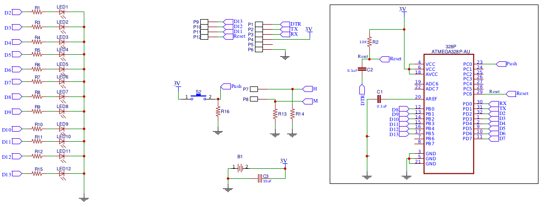
Schematic
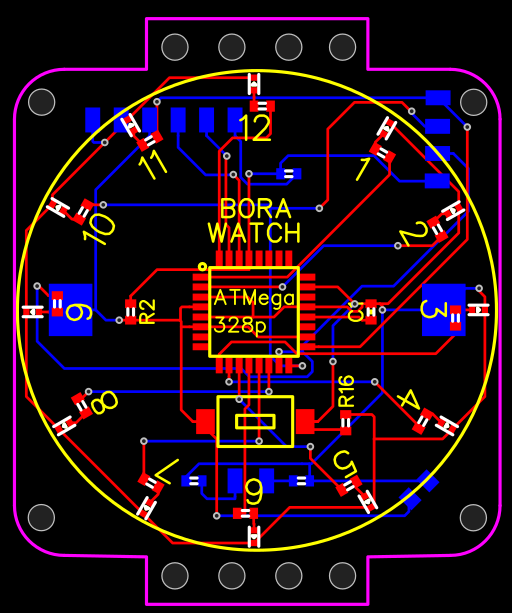
Board
It is basically an Atmega328p connected to 12 resistor and 12 leds, to a pushbutton, well configured the reset pin for the bootloader and programming (capacitor and resistor), the pins for programming (SPI and UART) and a battery holder for CR2032.
You can see in the online editor
Or from PDF,
PCB
Once you have the design of your board, you have to generate the GERBER files and order in your favorite manufacturer. In this case I choose the manufacture associated to this online designer, jlcpcb, but you could use another tool for design and generate the gerbers as Eagle and then, the manufacturer could be oshpark or seeedstudio, as examples
But jlcpcb it was fine, 10PCBs for ~7 euros.
Soldering
I’ve used a technique that I’ve never used before, with the soldering paste.
It is a paste you put in the PCB, you put the components on top of it, and then, ideally with a hot station but if you don’t have anything better with a hot gun, you reflow the components until the paste disappears with the metallic parts joined.
PCB with soldering paste,
PCB, paste and components
After apply the hot gun,
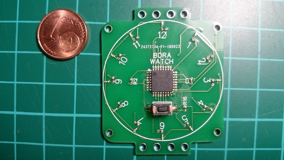
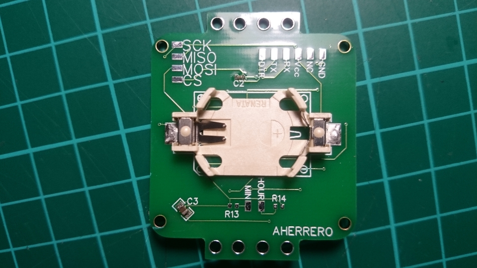
On the back,
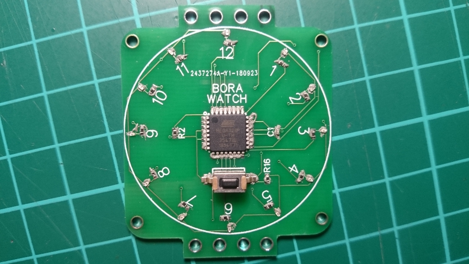
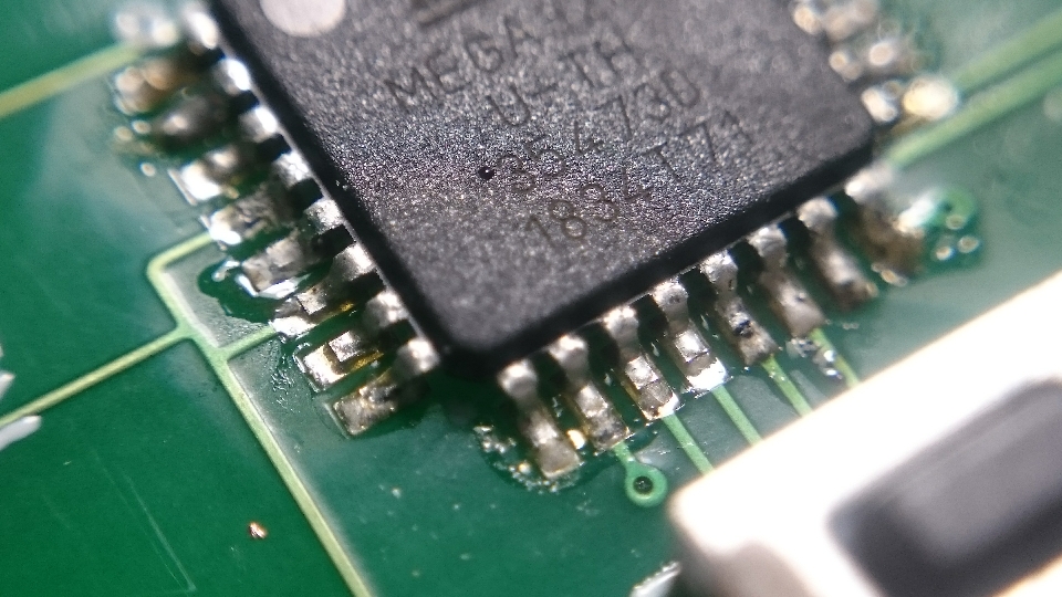
Atmega328p solder,
| Leds and resistors | resistor |
|---|---|
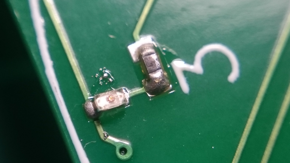 |
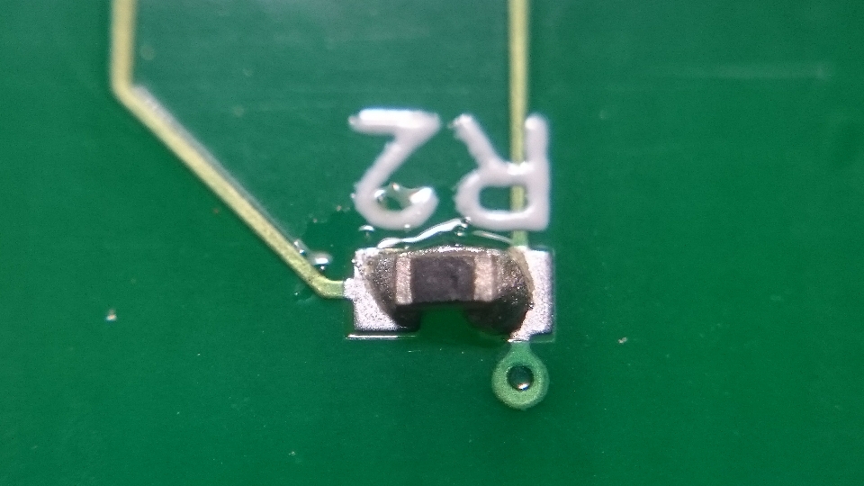 |
Something very important, you should check all the connection after make this procedure (Specially the correlated pins in the microcontroller, and both pins of capacitor and resistor if they are connected between them). It is probably that some components are bad solder and you have to finish the work manually.
Software
Bootloader
I’ve been playing with bootloader and programming since the last month for a few projects, so you may want to check this blog entries:
- Arduino to breadboard - Atmega328p. How to use the Atmega328p without the Arduino and with an external clock.
- Atmega328p without clock: Internal clock - Mhz
In these post I explain basically what we should to do here for having the Atmega328 with bootloader and programmed.
But one point missing: Connection to this watch.
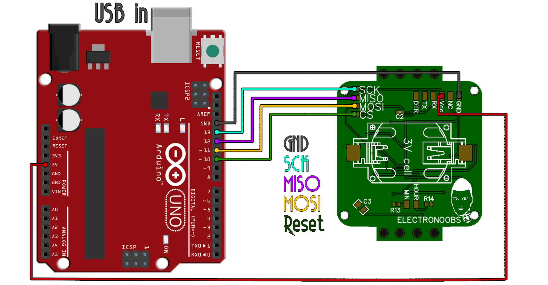
First, I’ve used Arduino as ISP for burning the bootloader in the watch. This is not the best programmer you should use, and if possible, you could use an AVR programmer.
If you are using an Arduino, as I’ve indicate in previous entries, be sure you have the 10 uF capacitor between reset and ground on the programmer
For burning the bootloader I’ve used the library MiniCore. I’ve selected the Arduino 328p, with internal 8Mhz clock and the BOD 1.8V (As we are going to use a small battery, we want to reduce the shutdown of the atmega to the minimum).
The complete instructions for the bootloader are also in the arduino official tutorial
Programming - Transfer the code
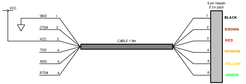
For programming the Arduino we have the UARTs pinout (RX,TX and DTR for the reset) on the watch. We only need an FTDI cable and connect as shown,
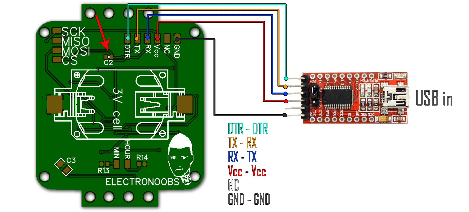
FTDI pinout,
In this case, we already have the 0.1uF capacitor between the reset and the DTR line, so, it is not necessary to add.
To send the code to the watch, we could use the Blink example, once we have the same board used for the bootloader, and changinig in the Arduino IDE from Arduino as ISP to AVRISP mkII. One of the leds (I don’t remember which corresponds to the pin13 in Arduino) is going to Blink, which means, we are able to send the program to our watch.
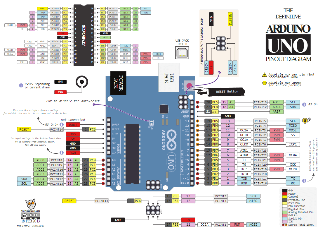
Some references with the pinout of the Atmega328p and the Arduino from circuito.io blog
And you can download the version of my code, as well ad the original version in my github.
I didn’t modify so much the source code, even if it seems there are some issues related with the clock (The time is going faster on this watch!) and also the hour programming is not working always. But it has interruption to wake up the Atmega328 when you press the button, and it only shows the hour when pressing the button.
Final results
Video:
Future
I’ve learned a lot in this (simple) project, but this doesn’t means I am going to stop here. There are several improvements we could perform in this project:
- The battery performance is not great. At all. As I’ve reduce the BOD to 1.8V (Mechanism to deactivate the Atmega328 when reach this voltage), we can use the watch more than the original project.. But still, the battery is for 3-4 days. Only showing a few leds sometimes during the day!
- The time is not correct 80% of the time. Using the internal clock is not the best idea if you want to have a constant clock for measuring the time. Instead, it is normally better using an external oscillator.. Or even better, a RTC Keyword: 32.768kHz. This is a Real-Time-Clock crystal. 32.768kHz means it is precisely half of a 16-bit counter. Start counting at 0x8000 (or 32768). When the counter rolls over from 65535 to 0, then you know that exactly one second has passed.
- Related with both topics: We could improve the time and the battery using a RTC: They consume very little, and we could really put the Atmega328p in sleep mode, so only wakes up when a button is pressed, read the time from the RTC, show the tiem and go to sleep again