Multiplexing Outputs with 74HC595 and atmega
Introduction
The atmega328 (Or whatever Arduino you want to use) may don’t have enough pins to control your project. But in the electronics world there are a few solutions to fix that.
The first solution seems better if you want to reduce to the minimum the number of pins.
The second solution, you will need 3 pins always, but, you could put several shift register in cascade within using the same 3 pins.
And the third solution, a different approach with matrix style.
Shift register - SN74HC595
I am going to use a shift register because I had some, but it could be not the best solution for your project.
As sparkfun describes, the SN74HC595N is a simple 8-bit shift register IC. This shift register is a device that allows additional inputs or outputs to be added to a microcontroller by converting data between parallel and serial formats. Your chosen microprocessor is able to communicate with the The SN74HC595N using serial information then gathers or outputs information in a parallel (multi-pin) format. Essentially it takes 8 bits from the serial input and then outputs them to 8 pins.
This SN74HC595N contains an 8-bit, serial-in parallel-out shift register that feeds an 8-bit D-type storage register with parallel 3-state outputs.
Using the SN74HC595
Normally, I prefer the tutorials from sparkfun but in this case, the tutorial from the Arduino webpage is great.
One shift register
Hardware.
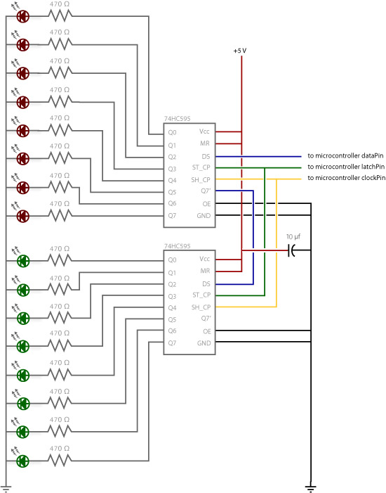
With the schema from the datasheet,
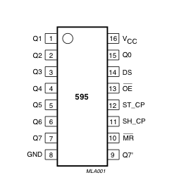
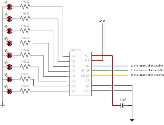
We can start cabling the shift register;
- VCC and MR pins to VCC
- GND and OE pins to ground
- DS (pin 14), data pin (blue cable in schematic), to Arduino 11.
- SH_CP (pin 11), clock pin (yellow cable in schematic), to Arduino 12
- ST_CP (pin 12), latch pin (green cable in schematic), to Arduino 8
After that, connect all the outputs (in this case, 8 leds) to the Q0-Q7 pins. Don’t forget the resistor before the led. Also, as recommendation, capacitor 10uF between VCC and GND.

Software
You could see the software explained in the Arduino webpage, but it is basically,
//Pin connected to ST_CP of 74HC595
int latchPin = 8;
//Pin connected to SH_CP of 74HC595
int clockPin = 12;
////Pin connected to DS of 74HC595
int dataPin = 11;

//holders for infromation you're going to pass to shifting function
byte data;
byte dataArray[10];

void setup() {
  //set pins to output because they are addressed in the main loop
  pinMode(latchPin, OUTPUT);
  Serial.begin(9600);

  //Binary notation as comment
  dataArray[0] = 0xFF; //0b11111111
  dataArray[1] = 0xFE; //0b11111110
  dataArray[2] = 0xFC; //0b11111100
  dataArray[3] = 0xF8; //0b11111000
  dataArray[4] = 0xF0; //0b11110000
  dataArray[5] = 0xE0; //0b11100000
  dataArray[6] = 0xC0; //0b11000000
  dataArray[7] = 0x80; //0b10000000
  dataArray[8] = 0x00; //0b00000000
  dataArray[9] = 0xE0; //0b11100000

}

void loop() {

  for (int j = 0; j < 10; j++) {
    //load the light sequence you want from array
    data = dataArray[j];
    //ground latchPin and hold low for as long as you are transmitting
    digitalWrite(latchPin, 0);
    //move 'em out
    shiftOut(dataPin, clockPin, data);
    //return the latch pin high to signal chip that it
    //no longer needs to listen for information
    digitalWrite(latchPin, 1);
    delay(300);
  }
}

// the heart of the program
void shiftOut(int myDataPin, int myClockPin, byte myDataOut) {
  // This shifts 8 bits out MSB first,
  //on the rising edge of the clock,
  //clock idles low

  //internal function setup
  int i=0;
  int pinState;
  pinMode(myClockPin, OUTPUT);
  pinMode(myDataPin, OUTPUT);

  //clear everything out just in case to
  //prepare shift register for bit shifting
  digitalWrite(myDataPin, 0);
  digitalWrite(myClockPin, 0);

  //for each bit in the byte myDataOut�
  //NOTICE THAT WE ARE COUNTING DOWN in our for loop
  //This means that %00000001 or "1" will go through such
  //that it will be pin Q0 that lights.
  for (i=7; i>=0; i--)  {
    digitalWrite(myClockPin, 0);

    //if the value passed to myDataOut and a bitmask result
    // true then... so if we are at i=6 and our value is
    // %11010100 it would the code compares it to %01000000
    // and proceeds to set pinState to 1.
    if ( myDataOut & (1\<\<i) ) {
      pinState= 1;
    }
    else {
      pinState= 0;
    }

    //Sets the pin to HIGH or LOW depending on pinState
    digitalWrite(myDataPin, pinState);
    //register shifts bits on upstroke of clock pin
    digitalWrite(myClockPin, 1);
    //zero the data pin after shift to prevent bleed through
    digitalWrite(myDataPin, 0);
  }

  //stop shifting
  digitalWrite(myClockPin, 0);
}
Two shift register
Now, the interesting topic is here: How to add a second shift register and therefore, as many shift register as your microcontroller can support.
Hardware.
We can start cabling the shift register;
- VCC and MR pins to VCC
- GND and OE pins to ground
- DS (pin 14), data pin (Connect this second data pin to the pin 9 from the first shift register)
- SH_CP (pin 11), clock pin (Same pin from Arduino, we could connect this directly to the first clock)
- ST_CP (pin 12), latch pin (Same pin also, connect to the first latch)
And that’s it! Then, you could connect the outputs to whatever you want to control.
Software
The differences between one register to two register or more is the array you could create to enable/disable pins (0-1) and the times you call the function shiftOut
void loop()
{
    // ...

    //load the light sequence you want from array
    data = dataArray[j];
    data2 = dataArray2[j];
    // data3 = dataArray3[j];    // --> multiply the array as many as shift register you have

    //ground latchPin and hold low for as long as you are transmitting
    digitalWrite(latchPin, 0);

    //move 'em out
    shiftOut(dataPin, clockPin, data);
    shiftOut(dataPin, clockPin, data2);
    // shiftOut(dataPin, clockPin, data3);  // --> multiply the times calling the function

    //return the latch pin high to signal chip that it
    digitalWrite(latchPin, 1);

    // ...
}
Real examples
I’ve developed two kind of examples to shows the possibilities of this output Multiplexing.
1. Random lights
- Connect 4 shift register in cascade.
- Connect 8 leds (and resistors) to the 8 outputs from the shift register
- Using an Arduino Uno, control every leds separately, but in a random way (It’s almost Christmas!!)
Software
Available in my github, TMR1v2_shiftRegister4Leds
Just,
shiftOut(dataPin, clockPin, random(255));
4 times (for the 4 register)
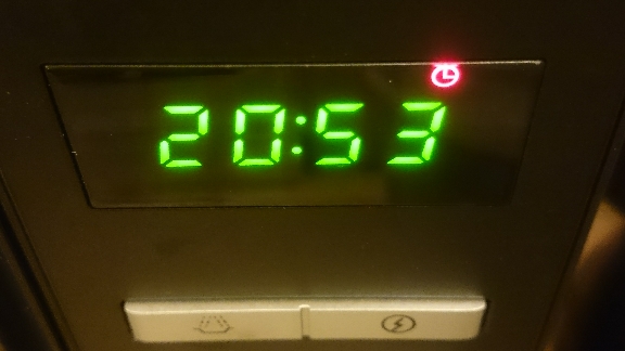
2. Wall clock
I’m getting obsessed with the watches, but I found it easy… And I need a wall clock =D
So, we could use the previous project with 4 displays 7-segments instead of 8 leds (There is 1 output that will be free from the register.. Or we could use the dot from the display)
And we could merge the project with the AtmegaWithRTC project, so we could have a nice and big watch.
Otherwise, we could continue using the watch from the microwave =D
Software
Software in my github, TMR1_v2_rtcLowDisplay
You have to be careful what leds you want to turn on / turn off.
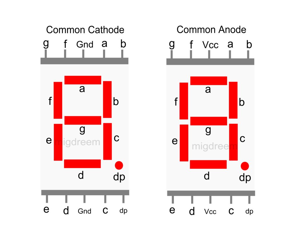
If you connect (Q0, …, Q6) from the shift register, with the segments (a,…, g) and your display is Common anode (VCC connected to display) the following array is applicable,
byte numbersToDisplay[] = {
    B11000000,  //  0
    B11111001,  //  1
    B10100100,  //  2
    B10110000,  //  3
    B10011001,  //  4
    B10010010,  //  5
    B10000010,  //  6
    B11111000,  //  7
    B10000000,  //  8
    B10011000  //  9
};
- The bit MSB is not used (always 1), as the array is filled with (Q7, Q6, …, Q0)
- The 0 turns on the led. The 1, turns off.
Then, you can write your own function to I set the time (In my software, set hour and minutes, but not seconds or the date) and show the time each 1 second.