Bora Watch v3 - Digital homemade wrist watch
[WORK IN PROGRESS…]
Introduction
A third iteration of my watch!
As improvements compare with the previous version, I did:
- The oscillator and RTC is now the same chip: A DS3231 RTC. Normally, this chip is an expensive a much dedicated chip for measuring the precise time, but I found it cheaper from China, and avoids the problem with the oscillator footprint. See my quick test for this RTC.
- The software change in consequence with this new RTC.
- As normally the watch is going to use 1 o 2 leds at the same time, I’ve reduced the number of resistor to 1, instead of 12. It will be a difference of intensity if 1 or 2 leds are at the same time, but it is a risk worth it.
- And must important, a redesign PCB to fit in a real watch enclosure. [todo picture enclosure]
Bill-Of-Materials
- 1 x ATMEGA328P-AU
- 1 x RTC DS3231SN
- 12 x LED 0402 Blue
- 1 x 470k 0402
- 4 x 10k 0402
- 1 x 100nF 0402
- 1 x Mini Pushbutton switch or https://www.sparkfun.com/products/10791
- 1 x Battery holder CR2332
Tools
PCB Design
This is the link for my project in eagle
If you don’t know eagle before, EAGLE is a scriptable electronic design automation (EDA) application with schematic capture, printed circuit board (PCB) layout, auto-router and computer-aided manufacturing (CAM) features
The free version includes: 2 schematic sheets, 2 signal layers, and an 80cm2 board. So normally, could be enough for prototype and hobby.
There are many solutions for schematics and PCB design but, why I choose Eagle?
First, the free solution. Even if it is not open source any more, it is enough for my purpose. With the same idea, I could choose Kicad
Then, the functionality offline, unlike some programs like Altium.
And finally, it is supported for my favorite manufacturer sparkfun where all their designs have a project with eagle free for download and ready if you want to use it.
And lot of tutorials!
- https://learn.sparkfun.com/tutorials/how-to-install-and-setup-eagle
- https://learn.sparkfun.com/tutorials/using-eagle-board-layout
- https://learn.sparkfun.com/tutorials/using-eagle-schematic
Schematics
The schematics is pretty simple:
- 12 Leds with the resistor
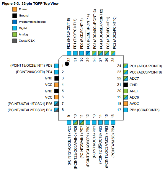
- Microcontroller Atmega328P
- RTC with 32.768 Oscillator integrated
- Battery CR2032 with the capacitor.
- Push button for displaying the time
- Test point for programming (ISP programming) and serial communication for Debug (RX,TX)
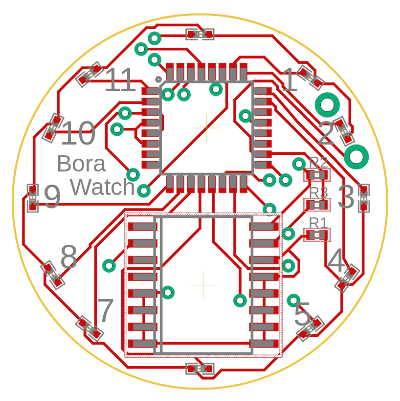
Board
| Top layer | Bottom layer |
|---|---|
|
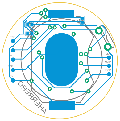 |
The board in pdf, top layer and bottom layer
Order
Once you generate the GERBERS, you can send them to the manufacturer to print the PCB.
- Seeedstudio. This time, I choose this manufacturer for the PCBs. They even have a tutorial about how to generate the gerbers, according to their specification, with eagle. Cost: $4.90 each 10 PCBs and $12.62 deliver to EU (Total: $17). Delivering time: 18 days.
- jlcpcb The last time I ordered here. The cost was $2 each 10 PCBs, and shipping $6.15 (Total: $8.15) Deliver time: Around 21 days.
The differences between them for the moment are; Seeedstudio seems more serious and they allow to manufacture PCB with other colors of PCB without extra cost. On the other hand, I don’t know if it is worth it compeering the price (Double than jlcpcb). Also, jlcpcb only cost $2 if you order only one design. For more design, they increase to $5 each.
Soldering
This time for soldering the atmega328, I have taken advantage of I am working in a electronics company for using a soldering microscope, so I could solder manually.
[todo…]
Software
You can find the software in github #TODO
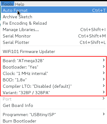
Bootloader
I’ve use the MiniCore library with Arduino to configure the fuses of the atmega, with the following configuration:
Programming
#TODO As you may have seen, there are 6 setpoints at the bottom, to connect the ISP for programming. Finally, as I programmed several times to get it works, I solder the pins and then remove it.
May attention the sense of the pins with the schematics and your ISP cable (Detect for example the VCC, with the battery, and compare the VCC with the cable)
Final results
#TODO
Improvements
#TODO