Bora Watch v2 - Digital homemade wrist watch
Introduction
I’ve made a second version for my digital watch!
After the first version, I’ve discovered several things I could improve, being the most important the time precision (Improving with a RTC) and the battery life (The external oscillator with the RTC allows the microcontroller go to the sleep mode)
Bill-Of-Materials
- 1 x PCB: GERBERS here, schematics and board, Designed with eagle 9.2.2, and manufactured in seeedstudio
- 1 x ATMega328p-AU: Amazon Atmega328p. Bought here because my usual provider didn’t have.
- 12 x 330R 0603 SMD resistors
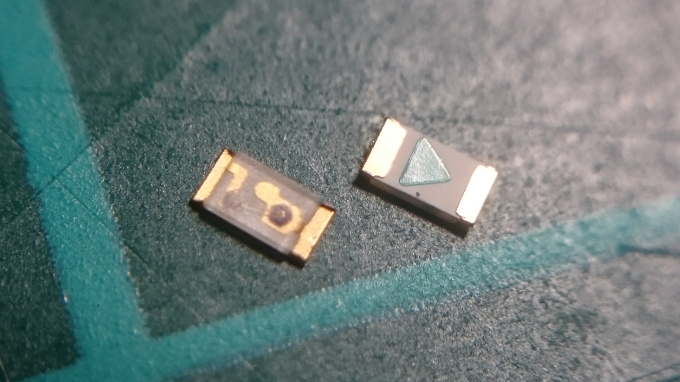
- 12 x 0603 SMD Red LED
- 1 x SMD Tactile Switch
- 4 x 10K 0603 SMD resistors
- 1 x 100nF 0603 SMD capacitor
- 1 x 10uF 0805 SMD capacitor
- 1 x Battery Holder CR2032
- 1 x Quartz 32.768 kHz
- 2 x 6.8pF 0805 SMD capacitor
- 1 x RTC MCP79410-I/SN SO-8
Tools
- Soldering Paste and needle
- Heat gun, although, I’ve realized that this one it wasn’t powerful enough, but it was fine.
- Velcro strip
- AVR programmer
PCB Design
In the first version I modify the design from the original project but this time, I’ve made my own design with eagle in order to include the RTC and also, because this time is entirely Bora Watch brand =D
This is the link for my project in eagle
If you don’t know eagle before, EAGLE is a scriptable electronic design automation (EDA) application with schematic capture, printed circuit board (PCB) layout, auto-router and computer-aided manufacturing (CAM) features
The free version includes: 2 schematic sheets, 2 signal layers, and an 80cm2 board. So normally, could be enough for prototype and hobby.
There are many solutions for schematics and PCB design but, why I choose Eagle?
First, the free solution. Even if it is not open source any more, it is enough for my purpose. With the same idea, I could choose Kicad
Then, the functionality without network connection, unlike some programs like Altium.
And finally, it is supported for my favorite manufacturer sparkfun where all their designs have a project with eagle free for download and ready if you want to use it.
And lot of tutorials!
- https://learn.sparkfun.com/tutorials/how-to-install-and-setup-eagle
- https://learn.sparkfun.com/tutorials/using-eagle-board-layout
- https://learn.sparkfun.com/tutorials/using-eagle-schematic
Schematics
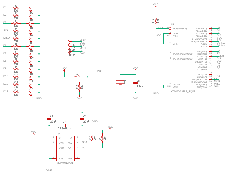
The schematics is pretty simple:
- Leds with the resistor
- Microcontroller Atmega328P
- RTC with 32.768 Oscillator.
- Battery CR2032 with the capacitor.
- Push button for displaying the time
- Test point for programming (ISP programming)
- And just on top, J1-J4, they are only connectors I am going to use to tie the watch strap so, no electrical functionality.
I’ve also discover two problems in the schematics after ordering the pcb:
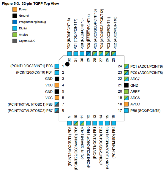
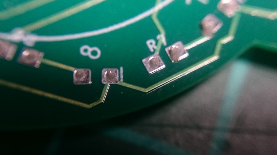
- According to the atmega328 specification, the chip has ADC6 and ADC7 pins but I’ve realized they only work as input for voltage references, not as output, so, I can’t use them to control the leds. I was forced to change this pins to SCK and MISO with cables. In the github, the schematics are now correct, but the gerbers were sent with this mistake.
- The footprint for the oscillator 32.768 wasn’t correct for the oscillator I have. So, I have improvised something.
Board
| Top layer | Bottom layer |
|---|---|
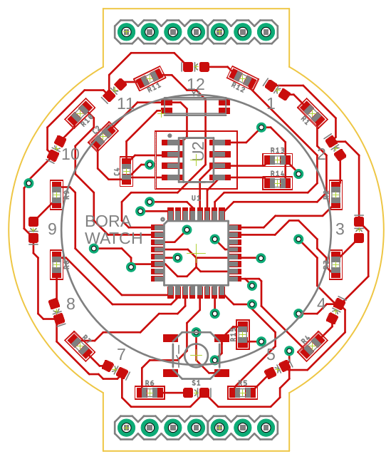 |
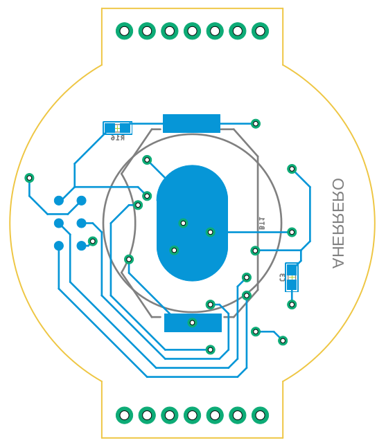 |
The board in pdf, top layer and bottom layer
Order
Once you generate the GERBERS, you can send them to the manufacturer to print the PCB.
- Seeedstudio. This time, I choose this manufacturer for the PCBs. They even have a tutorial about how to generate the gerbers, according to their specification, with eagle. Cost: $4.90 each 10 PCBs and $11.27 deliver to EU (Total: $16,17). Delivering time: 24 days.
- jlcpcb The last time I ordered here. The cost was $2 each 10 PCBs, and shipping $6.15 (Total: $8.15) Deliver time: Around 21 days.
The differences between them for the moment are; Seeedstudio seems more serious and they allow to manufacture PCB with other colors of PCB without extra cost. On the other hand, I don’t know if it is worth it compeering the price (Double than jlcpcb)
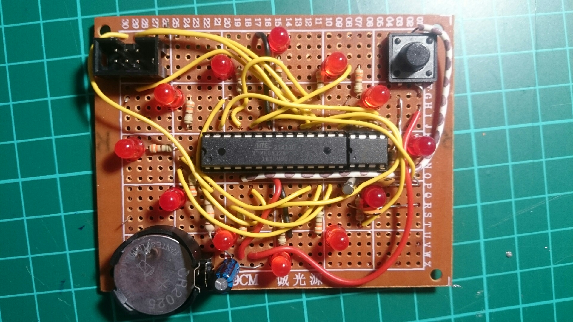
Fast prototype
In the meantime waiting for the PCB arrives and in order to develop the software, I built a prototype, using the same atmega328 and same RTC MCP7940M
Soldering
This time for soldering the atmega328, I have taken advantage of I am working in a electronics company for using a soldering microscope, so I could solder manually.
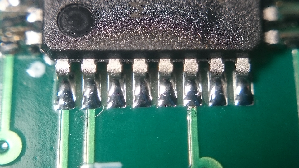
For the other components, as it was faster and I didn’t need precision, I use again the soldering paste.
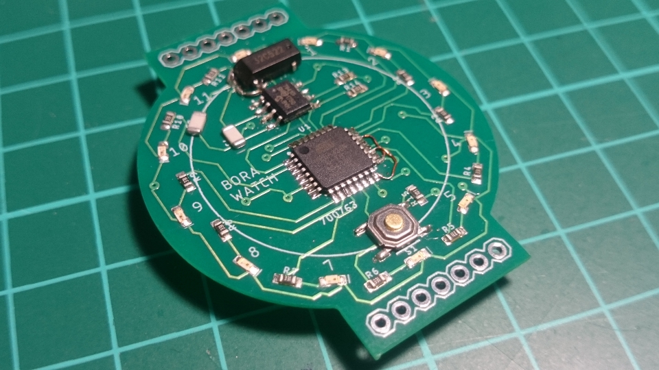
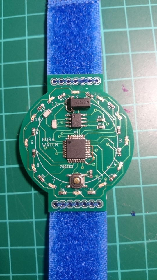
So, the final result,
| Top | Bottom |
|---|---|
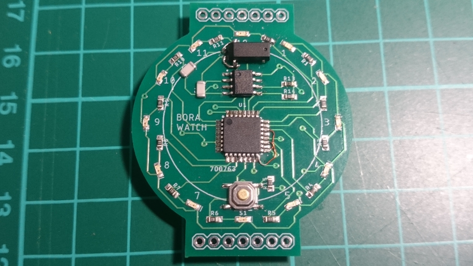 |
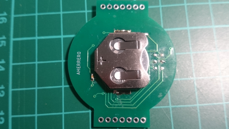 |
Software
You can find the software in github
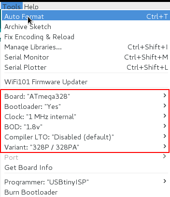
Bootloader
I’ve use the MiniCore library with Arduino to configure the fuses of the atmega, with the following configuration:
Programming
As you may have seen, there are 6 setpoints at the bottom, to connect the ISP for programming. Finally, as I programmed several times to get it works, I solder the pins and then remove it.
May attention the sense of the pins with the schematics and your ISP cable (Detect for example the VCC, with the battery, and compare the VCC with the cable)
Final results
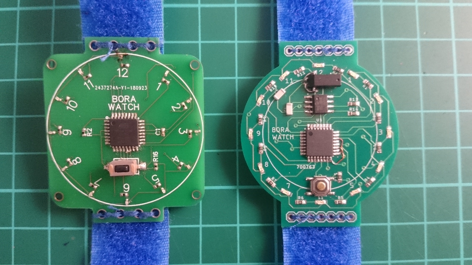
Once the velcro strip has been sewn,
And if I compare with the previous version,
Improvements
Obviously, the first fix will be:
- Redesign the PCB with the ADC pins correctly.
- A correct oscillator or a correct footprint.
And then, another improvements I was thinking on:
- As I use one or maximum two led at the same time, we could use only one 330 ohm resistor in order to simplify the circuit.
- The footprint for the component 0402 (led, resistor and capacitor) is not correct in eagle, so, we could use this size of component if we fix the footprint.
- A nice enclosure printed in 3D, similar to this project