Timer 555
Introduction
I’ve remember when I learned about oscillators, multivibrators, flip-flop and so on in the university, it wasn’t pleasant at all..
Example of what horrified me:
Astable Multivibrator tutorial
But then, I’ve heard how the people of hackaday talks about the Timer 555 as a reference in sentences like:
“An Arduino for that?? I could use a 555 and it will better than your project”
So, I’ve decided to investigate.
What is the timer 555
The wikipedia says:
The 555 timer IC is an integrated circuit (chip) used in a variety of timer, pulse generation, and oscillator applications. The 555 can be used to provide time delays, as an oscillator, and as a flip-flop element.
In other worlds, it is a small chip, not at all expensive, and very old in the market (From 1970!) but very used in all kind of applications.
The IC 555 has three operating modes: Astable, Monostable and Bistable.

You can read the datasheet from Texas Instruments
How to use it
This tutorial includes good examples about how to use the timer 555 even if there are hundreds of examples.
On the other hand, the http://www.555-timer-circuits.com/ page describes everything we want to know about this little thing.
And of course, the tutorials from sparkfun can’t miss.
Basic Astable 555 Oscillator Circuit
We are going to build a basic astable with the timer 555. For that, I have two references:
This is a basic layout:
And the formules to calculate the passive components in function of how much frequency, duty cycle etc, you want

With this calculator, we can calculate the passive components that we want for our cycle.
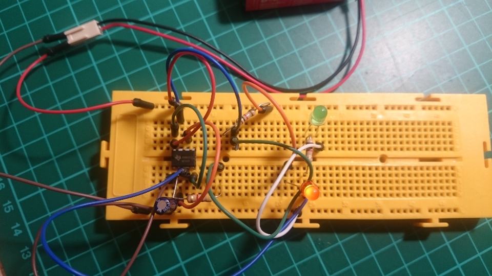
In this case, for a cycle high and low around 350ms each, I choose the components:
- C = 100uF
- R1 = 1k
- R2 = 4.7K
Testing
| Simple Output | Double Output |
|---|---|
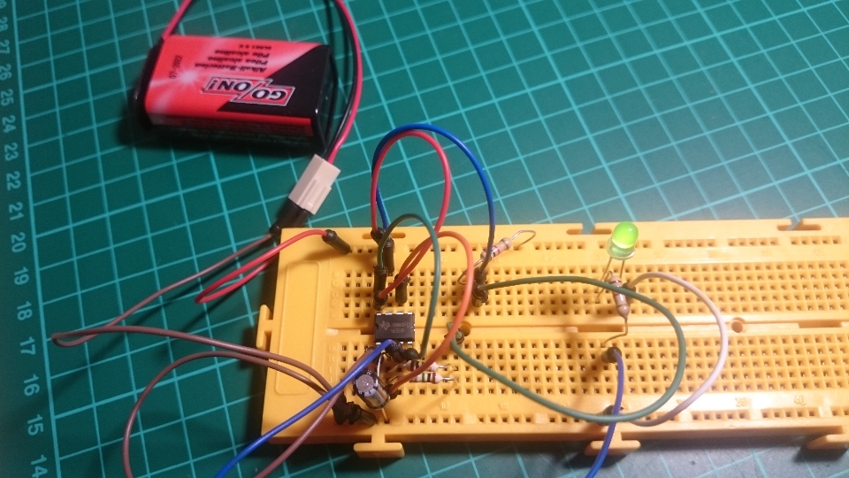 |
 |
Video:
.
More projects
- Build a robot. (Ok, it is not a robot, but appears a nice robot)
- One of the smallest blinking circuit I see, which I will try soon..
- In 555-timer-circuits you will find several examples.
- A practical example when our fridge is not working well enough.