IoT Automatic Plant Watering - v1
IoT Automatic Plant Watering - v1
The goal of this project is to automate the plant watering, measuring the soil moisture and activating the pump motor if the plant needs water.
[UPDATE] Second prototype with limit current protection, here
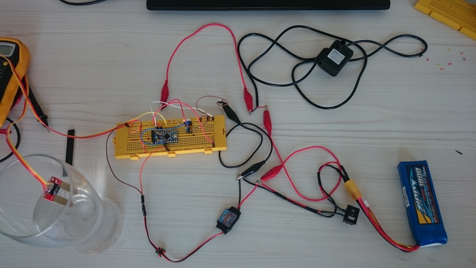
Prototype v0.1
Material used
- Arduino Pro Mini 5V
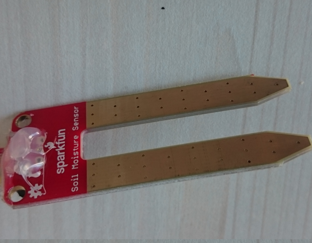
- Soil Moisture Sensor
- Mosfet IRF540N
- Resistor 10k
- UBec
- 11.1V to 5V
- Lipo 1800mAh
- 11.1V
- 20C
- Pump motor
- Input DC 3.5-9V, 1-3W
- Hmax 0.4-1.5m
- Qmax 200L/H
Instructions
Pump motor control
The first problem is control the pump motor, which needs 3.5 to 9V of input and up to 3W. This means, we will need an extra power supply which doesn’t come from the Arduino (Arduino gives an ouput of 5V, which could be fine, but a current between 40-200mA).
As an external power supply, we should use another power supply than a Lipo, because the Lipo batteries give so much current. But if you don’t have anything similar at home…
This is the circuit:
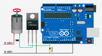
More information: http://bildr.org/2012/03/rfp30n06le-arduino/
Read the soil moisture sensor
We can read this sensor as any other analogic sensor.
https://www.arduino.cc/en/Tutorial/ReadAnalogVoltage
The difficulty, you should “calibrate” the sensor, measuring when the plant needs water.
The threshold for me was 800 (from a 1024 ADC values)
Also, if you are going to use the system outside, you probably want cover the sensor from the water:
Power
The ubec was used to reduce the voltage from the Lipo (11V-12V) to 5V. Although the Arduino accepts 5V, it’s the input limit, so, just in case.
The ubec has in the inputs the lipo, and the output the Arduino.
The lipo is connected directly to the pump motor (Reminder, the pump motor input voltage should not pass the 9V) so, we use the PWM to “limit” the voltage (This means, the PWM that normally can write from 0 to 255, we won’t use the 255)
Code
#include <LowPower.h>       //Library to sleep the micro

/*
 * Input/Output
 */

int inMoistureSensor = 1;    //Analog: Read Sensor
int pinOnMoistureSensor = 2; //Digital: on/off sensor
int outControl = 3;          //PWM Digital: Motor output
int pinInternalLed = 13;     //Digital: Led output (internal) used as indicator

/*
 * Var
 */

int motorSpeed = 255;

/*
 * Functions
 */

int getMoistureValue()
{
  // sensor temperature
  int sensorMoisture = analogRead(inMoistureSensor);
  //Serial.print(sensorMoisture); Serial.println(" raw value.");
  return sensorMoisture;
}

/*
 * setup()
 */
void setup()
{
  Serial.begin(9600);                   //Start the serial connection with the computer

  pinMode(pinOnMoistureSensor, OUTPUT); //pin to power on the sensor
  pinMode(outControl, OUTPUT);          //pin to control de pump motor

  pinMode(pinInternalLed, OUTPUT);      //led to show if the pump motor is working
}


/*
 * loop()
 */
void loop()                     // run over and over again
{
  //Show the micro wakes up
  digitalWrite(pinInternalLed, HIGH);

  //Power on the moisture Sensor
  digitalWrite(pinOnMoistureSensor, HIGH);
  delay(100);

  //Read Sensor
  int sensorMoisture = getMoistureValue();

  //Action
  int firstAction = 0;
  while(sensorMoisture < 800)   //emperic value to determinate if the plant needs water
  {
    //Notify the pump motor is running with blink
    digitalWrite(pinInternalLed, LOW);
    delay(100);

    //Run pump motor
    if(firstAction == 0)
    {
      analogWrite(outControl, motorSpeed);
      firstAction = 1;
    }

    //Update sensor value
    sensorMoisture = getMoistureValue();

    //Blink
    digitalWrite(pinInternalLed, HIGH);
    delay(100);
  }

  //Power off pump motor
  analogWrite(outControl, 0);

  //Show the micro is going to wait
  digitalWrite(pinInternalLed, LOW);

  //Power off the moisture Sensor
  digitalWrite(pinOnMoistureSensor, LOW);
  delay(100);

  //Main Sleep
  delay(2000);

  //Sleep for 8s
  //LowPower.powerDown(SLEEP_8S, ADC_OFF, BOD_OFF);
}
Results
The circuit is working, the sensor reads the moisture, and when the mositure has a level less than “800” (ADC, input raw value), the pump motor start to work. Otherwise, the Arduino sleeps until the next interaction to read the value.
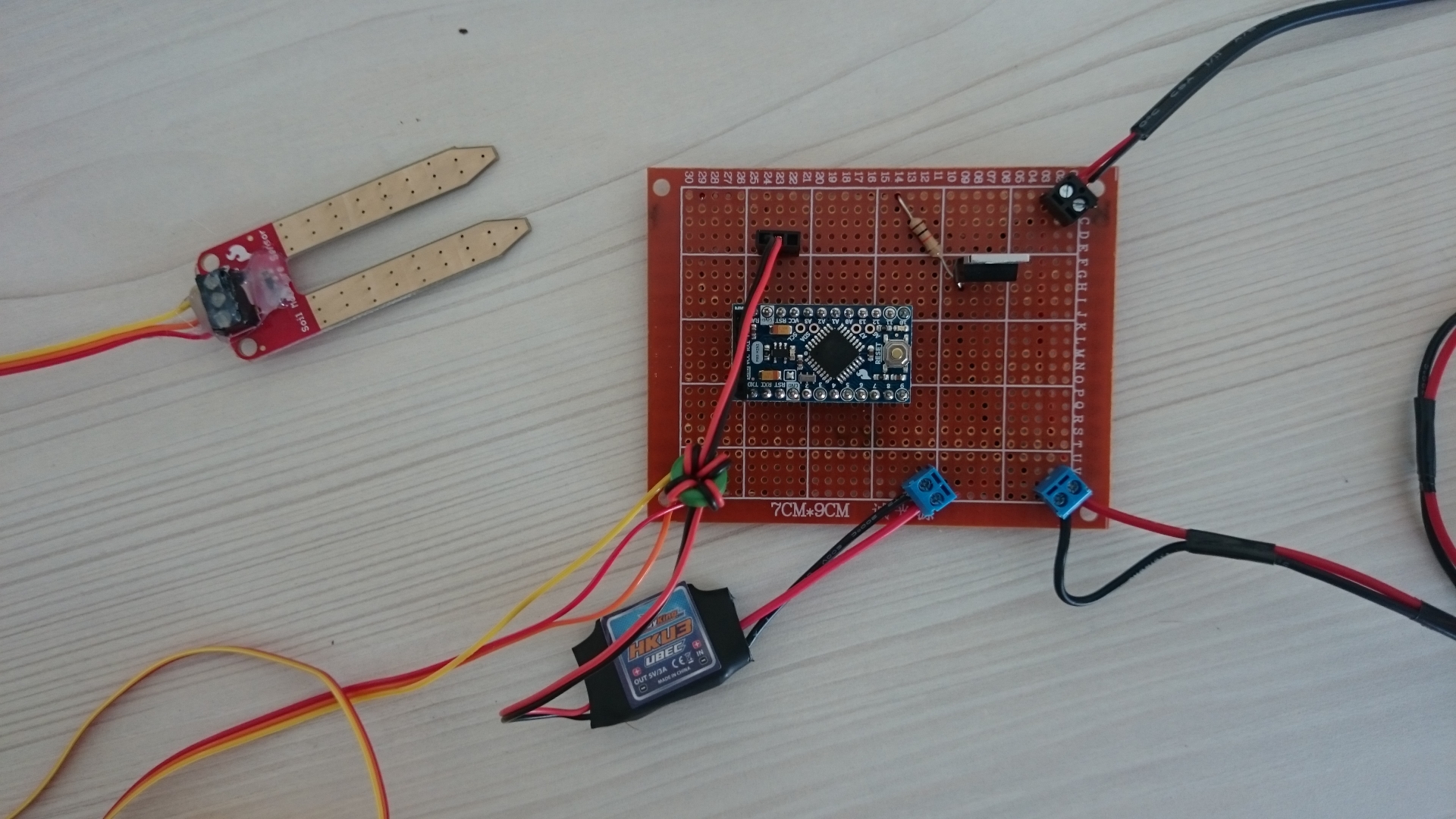
Prototype v0.2
In this prototype, we use the same circuit but, as the intention is to work outside, this circuit will be “less” prototyping.
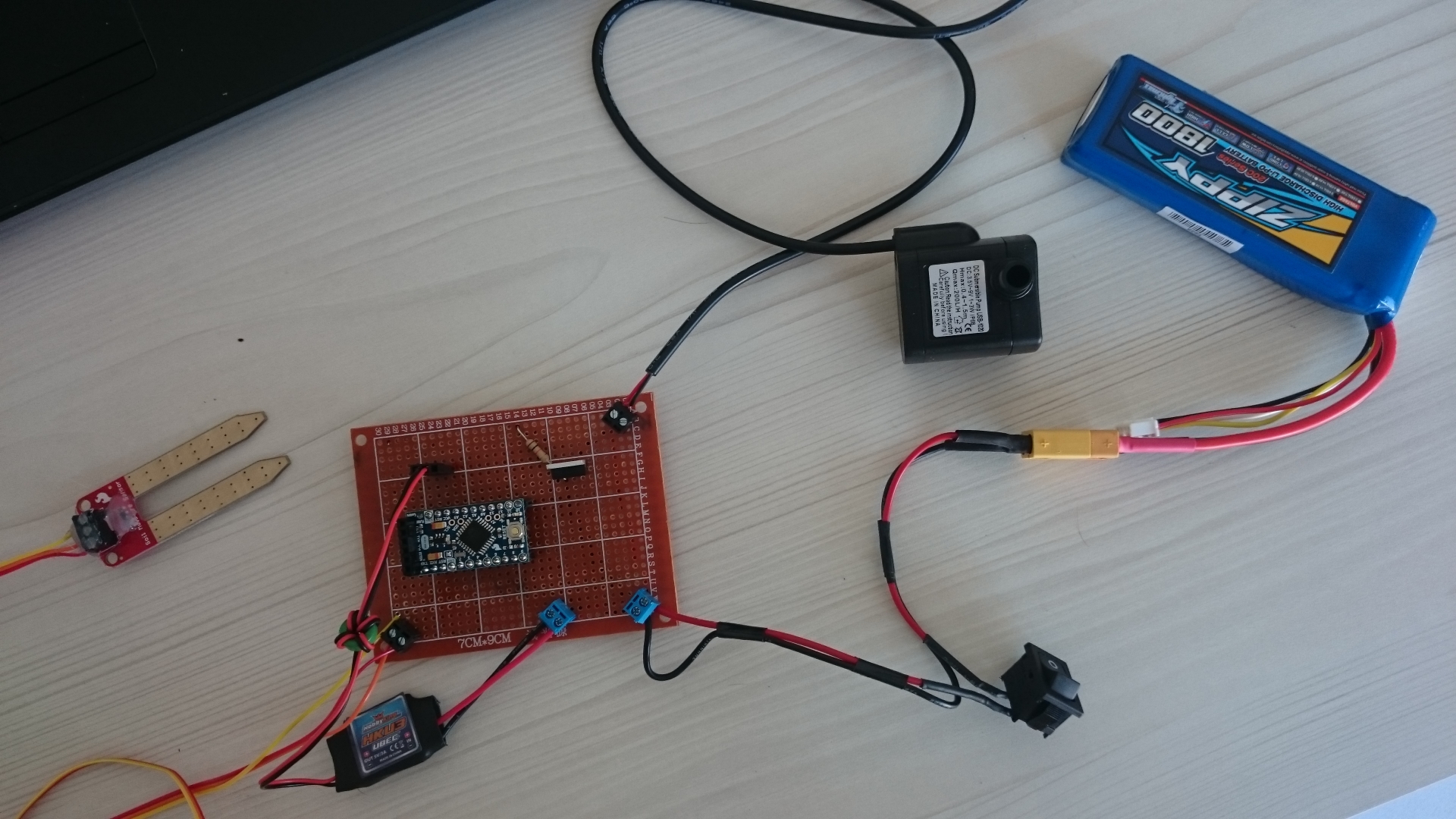
More in detail
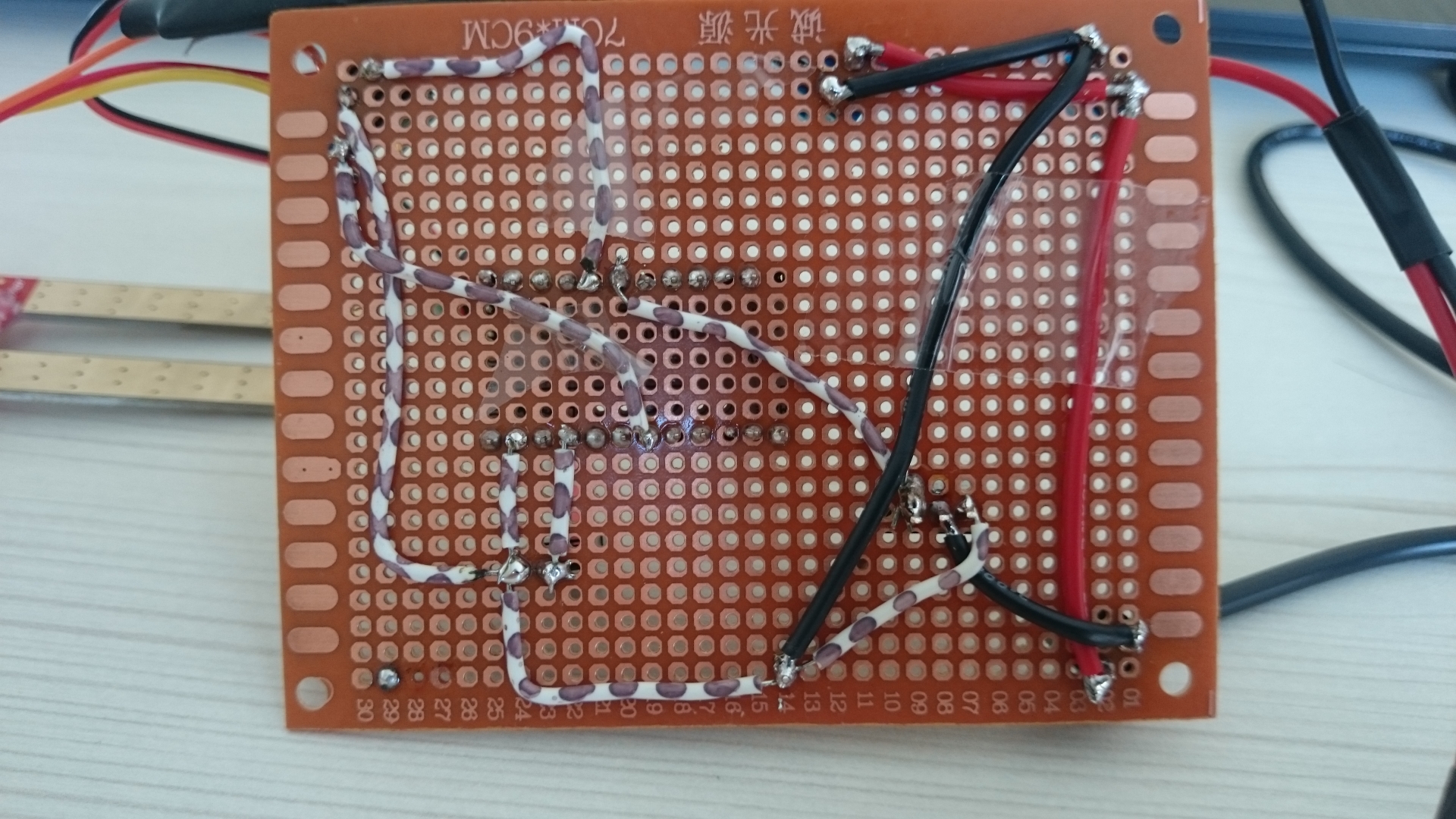
And from the back,
Conclusion
The complete circuit works for a short period of time, then, the pump motor broke. This could be due a different possibilities:
- There is no diode between the positive and negative of the pump motor. The diode should helps to avoid the reverse voltage when we stop the motor.
- The current is too high. Remember, the power supply used for all the circuit is a Lipo, and the Lipo battery will give us as much as current as the circuit needs. If the pump motor hasn’t a curret limiter, which probably has not, we are the responsible to limit this current with another way.
Possible improvements
- Diode between positive and negative in the pump motor.
- Current limiter with a motor controller type L298N. The problem with that is, we don’t need run the motor in the opposite direction and the motor may consume more than the motor controller can give us (Typically, the L298N gives 0.5A)
-
Current limiter with LM317. The circuit would be:
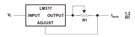
It’s a good alternative, but in that moment, I didn’t have the material to do it, so, let’s see another possibility. (More information, http://www.ti.com/lit/ds/symlink/lm317.pdf and http://www.techlib.com/electronics/regulators.html)
-
Current limiter with L7812. The circuit will be
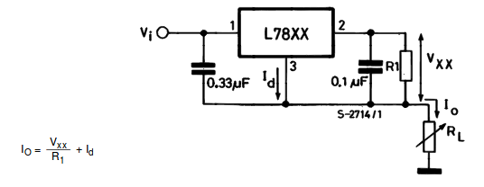
As alternative of the LM317, it’s a good solution. This solution will be implemented in the next iteration Version 2